|
Expansion of Hong Kong International Airport into a Three-Runway System |
|
|
Section Title
Appendices
Appendix A. Tentative Design Typical Cross Section of Seawall and Land Formation over CMPs
Appendix B. Reference Photographs of DCM Barges
Appendix C. Calculations of Total Sediment Loss
Appendix D. DCM Water Quality Monitoring Data Record Sheet
Tables
Figures
Charts
|
Chart 5.1:__ Flow Chart for DCM Specific Monitoring Parameters (Intensive) Chart 6.1:__ Flow Chart for DCM
Specific Monitoring Parameters (Regular)
|
1
Introduction
|
1.1
Background
Under the Environmental Impact Assessment Ordinance, the Environmental Impact Assessment (EIA) Report (Register No.: AEIAR-185/2014) prepared for the “Expansion of Hong Kong International Airport into a Three-Runway System” (the project) has been approved by the Environmental Protection Department (EPD), and an Environmental Permit (Permit No.: EP-489/2014) has been issued for the project. Pursuant to Condition 2.17 of the Environmental Permit (EP), the Airport Authority Hong Kong (AAHK) shall prepare a Detailed Plan on Deep Cement Mixing to present the monitoring arrangements and mitigation measures to be applied to Deep Cement Mixing (DCM) activities of the project.
Mott MacDonald Hong Kong Limited (MMHK) was appointed by AAHK as the Environmental Team (ET) and one of the tasks of the ET is to establish a Detailed Plan on Deep Cement Mixing (DPDCM) to avoid adverse water quality impacts and disturbance to marine mammals due to the DCM works.
1.2
Project Description
This project covers the expansion of the existing airport into a three-runway system (3RS) with key project components comprising land formation of about 650 ha with ground improvement and all associated facilities and infrastructure including taxiways, aprons, aircraft stands, a passenger concourse, an expanded Terminal 2, all related airside and landside works, associated ancillary and supporting facilities, diversion of aviation fuel pipelines and diversion of submarine 11kV cables.
1.3
Purpose & Scope
As specified in Condition 2.17 of the EP:
“The Permit Holder shall, no later than 3 months before the commencement of reclamation related marine works of the Project, submit 3 hard copies and 1 electronic copy of a detailed plan (The Plan) containing at least a layout arrangement and monitoring programme on Deep Cement Mixing (DCM) during the construction to the Director for approval. The Plan shall include monitoring locations, monitoring frequency, event and action plan for DCM process, and mitigation measures to be taken to avoid adverse water quality impacts and disturbance to marine mammals.”
The DPDCM, presented in Sections 2 to 7, details the environmental monitoring arrangements related to DCM during the 3RS Project construction phase to be implemented by the ET as part of the statutory environmental monitoring and audit (EM&A) programme, as well as the mitigation measures to be implemented by all DCM-related Contractors under the 3RS Project, and has been prepared in accordance with the EP requirements. In particular, this Plan covers the following:
¡ Water quality monitoring programme for DCM works
¡ Water quality monitoring locations, parameters and equipment
¡ Arrangements for initial intensive DCM monitoring and regular DCM monitoring
¡ Event and action plan
¡ Mitigation measures to be implemented as part of the DCM process
1.4
Report Structure
Following this introductory section, this DPDCM is structured as follows:
Section 2 Overview of DCM Works for 3RS Project
Section 3 Water Quality Monitoring Requirements
Section 4 Baseline Monitoring
Section 5 Initial Intensive DCM Monitoring (including the event and action plan)
Section 6 Regular DCM Monitoring (including the event and action plan)
Section 7 Mitigation Measures
2.1
General
DCM has been recommended in the approved EIA report as the ground improvement method to be adopted over the contaminated mud pit (CMPs), as it enables in-situ stabilisation of the CMPs which is considered to be a more environmentally suitable option compared to other ground improvement methods. However, this method has not previously been adopted in Hong Kong, despite extensive use in other countries where it has demonstrated no significant impact on water quality. Site trials of DCM were conducted by AAHK in the past and these trials have demonstrated no exceedance or elevation of suspended solids or any adverse water quality impacts attributable to the DCM works, and also no leakage of contaminants from the CMPs. Nevertheless, it is recognised that full scale ground improvement works over the completed and capped CMPs may entail some risks to water quality, hence there is a need to implement a water quality monitoring programme for the DCM works to ascertain the environmental acceptability of the DCM activities for 3RS Project.
2.2
Implementation of DCM for the 3RS Project
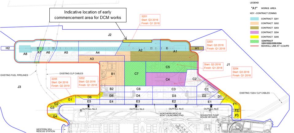
In accordance with the EP condition 2.31(ii), DCM is the ground improvement method for CMP areas to replace conventional seabed dredging for land reclamation works. The DCM process involves in-situ strengthening of the marine sediment within the CMPs via injection and mixing of cement slurry under a sand blanket layer. As part of ongoing detailed design, DCM will also be adopted in non-CMP areas for ground improvement. Based on latest information at the time of preparation of this Plan, there will be five main DCM contracts covering six DCM contract areas (in both CMP and non-CMP areas). The tentative locations and programme of each DCM contract is shown in Figure 2.1.
The exact locations and timing for implementing DCM are subject to detailed plan of future DCM Contractors for the 3RS Project.
|
|

Note:
The non-specified (‘green’) contract area (works area C5 & C7) for DCM
works is subject to undertaking by one of the four main DCM contracts (to be
determined).
For DCM works deployed under the 3RS Project, the following general construction sequence will apply:
i. Laying of sand blanket over the seabed
ii. Positioning of the DCM barges to the DCM clusters / panels
iii. Penetration of DCM shafts until it reaches the designed depth below the seabed
iv. Commencement of cement slurry injection with simultaneous mixing and withdrawal of DCM shafts
v. Termination of cement slurry injection when the withdrawal process reaches the sand blanket
vi. Laying of geotextile over the sand blanket along seawall areas and designated areas
vii. Commencement of marine filling or seawall construction activities
Tentative design cross-section for the new seawall and land formation over CMPs is shown in Appendix A. Reference photographs of different types of DCM barges are shown in Appendix B. Prior to commencement of full scale DCM works, various trials for equipment testing and calibration will be conducted on site at individual DCM barges.
2.3
Environmental Concerns related to DCM
Based on the approved EIA report, the main environmental concerns related to DCM activities and the associated EM&A requirements to address these concerns are summarised in Table 2.1.
Table 2.1: Summary of Environmental Concerns and Associated EM&A Requirements
|
Environmental Concern |
Summary of Evaluation from Approved EIA Report |
EM&A Requirements |
|
Release of suspended solids (SS) due to DCM activities |
DCM field trial in February 2012 showed no exceedance or elevation of SS attributable to the DCM installation works. |
Water quality monitoring at impact and sensitive receiver stations |
|
Potential risk of contaminant release from pore water during ground improvement via DCM within the CMP areas |
The worst case scenario of 100% pore water release from CMPs was modelled and the findings showed no exceedance of water quality criteria for all contaminants |
Initial intensive DCM monitoring of nutrients and heavy metals for a group of DCM rigs, followed by regular DCM monitoring for two representative heavy metals (with feedback mechanism for re-initiation of intensive DCM monitoring should exceedances be identified) |
|
Rise in water temperature associated with the exothermic process of in-situ cement mixing |
Not considered to be significant as heat dissipation will occur within the mud layer surrounding the DCM column and any minor heat dissipation through the upper ends of the DCM column will be absorbed by the 2m sand blanket on top of the seabed |
Initial intensive DCM monitoring of temperature for a group of DCM rigs |
|
Disturbance to marine mammals during DCM activities (e.g. due to underwater noise) |
DCM field trial in February 2012 showed almost no detectable increase in background noise levels beyond a distance of 250m, and the typical frequency is below 200 Hz which is a frequency of low sensitivity to Chinese White Dolphins |
Implementation of 250m dolphin exclusion zone (DEZ) |
|
Potential impacts from accidental spillage of chemicals / chemicals waste into the marine environment |
Mitigation measures are recommended for storage of chemicals and storage / disposal of chemical waste during construction phase |
Regular site inspections and audit |
Mitigation measures have been recommended in the approved EIA report to address the potential environmental impacts associated with DCM activities. These are extracted and presented in Section 7.
2.4
Comparison of the Latest Design Arrangements for DCM Against
the Approved EIA Report
2.4.1
Total Sediment Loss
In the approved EIA report for 3RS Project, the peak of DCM activities coincide with the peak of marine filling activities. However based on latest design arrangements, the peak of DCM activities would occur in Q2 2017, before the peak of marine filling activities, which is anticipated to be in Q1 2018. There would thus be two separate peaks (one for DCM and one for marine filling).
The approved EIA report for 3RS Project assessed the total sediment loss arising from a combination of sand blanket laying, marine filling and DCM works during the worst case (peak construction period) to be no greater than 4,348,969 kg/day[1].
Based on the latest estimate of plant numbers during the two updated worst case scenarios (DCM peak and the marine filling peak respectively), the total daily sediment loss has been re-calculated, and is shown in Appendix C. The results show that the total daily sediment loss arising from each updated worst case scenario is no greater than the original EIA worst case assumption, hence the update to the construction programme does not affect the findings of the approved EIA report for 3RS Project in terms of sediment loss.
2.4.2
Contaminant Release
The findings of the approved EIA report for 3RS Project on contaminant release from pore water during DCM works found that the worst case concentrations at WSRs (based on 42 nos. of DCM rigs and minimum dilution potential) would be well under the criteria levels, with the predicted highest contaminant concentrations being less than 4% of their respective criteria value[2].
Based on the latest design arrangements, the number of DCM rigs working within the CMPs is increased by approx. 48% (from 42 to 62 nos.). While the number of DCM rigs has increased, the potential additional pore water release and the accordingly increased predicted highest contaminant concentrations at WSRs would still remain well below the criteria values as the predicted highest contaminant levels in the approved EIA are only small fractions of the respective criteria. The number of DCM rigs to be deployed in the works hence does not affect the findings of the approved EIA report for 3RS Project in terms of compliance with criteria values for contaminants due to release of pore water from the CMPs.
3
Water
Quality Monitoring Requirements
|
3.1
Scope of Water Quality Monitoring for DCM Works
3.1.1
Types of DCM Monitoring
Environmental monitoring for the DCM activities have been specified as part of the EM&A requirements in the Updated EM&A Manual, which is available on the dedicated 3RS website http://env.threerunwaysystem.com/en/ep-submissions.html. The monitoring requirements for DCM activities are divided into the following three types:
¡ Baseline Monitoring – to obtain baseline water quality in the absence of all construction activities for 3RS Project.
¡ Initial Intensive DCM Monitoring – to undertake in-depth monitoring of a specific group of DCM rigs for a minimum duration to ascertain the environmental acceptability of the DCM works.
¡ Regular DCM Monitoring – to maintain regular monitoring on DCM activities for the duration of DCM works and provide a mechanism for re-initiation of intensive DCM monitoring where necessary.
3.1.2
Water Quality Parameters to be Monitored
For each type of monitoring related to DCM works, the water quality parameters to be monitored are summarised in Table 3.1.
Table 3.1: Water Quality Parameters
|
Water Quality Parameters |
Baseline Monitoring |
Initial Intensive DCM Monitoring |
Regular DCM Monitoring |
|
Dissolved Oxygen (DO) / Dissolved Oxygen Saturation (DO%) |
ü |
ü |
ü |
|
pH |
ü |
ü |
ü |
|
Temperature |
ü |
ü |
|
|
Salinity |
ü |
ü |
ü |
|
Turbidity |
ü |
ü |
ü |
|
Suspended Solids (SS) |
ü |
ü |
ü |
|
Total Alkalinity |
ü |
ü |
ü |
|
Nutrients |
|
|
|
|
Ammonia as N |
ü |
ü |
|
|
Unionised ammonia (NH3)* |
ü |
ü |
|
|
Nitrite as N |
ü |
ü |
|
|
Nitrate as N |
ü |
ü |
|
|
TKN as N |
ü |
ü |
|
|
Total Phosphorus |
ü |
ü |
|
|
Reactive Phosphorus |
ü |
ü |
|
|
Heavy Metals |
|
|
|
|
Cadmium (Cd) |
ü |
ü |
ü (two representative heavy metals) |
|
Chromium (Cr) |
ü |
ü |
|
|
Copper (Cu) |
ü |
ü |
|
|
Nickel (Ni) |
ü |
ü |
|
|
Lead (Pb) |
ü |
ü |
|
|
Zinc (Zn) |
ü |
ü |
|
|
Arsenic (As) |
ü |
ü |
|
|
Silver (Ag) |
ü |
ü |
|
|
Mercury (Hg) |
ü |
ü |
*Note: Calculation based on the laboratory result of ammonia nitrogen (NH4-N) and in-situ measured pH, salinity and temperature.
Legend:
“ü” denotes that the parameter will be monitored.
In addition to the aforementioned water quality parameters, the water depth, current speed and direction at each monitoring location will also be monitored and recorded.
3.2
Monitoring Equipment and Procedures
Monitoring of DO, DO%, pH, temperature, turbidity, salinity, and total alkalinity as well as water depth, current speed and direction should be measured in-situ / on-site whereas SS, heavy metals and nutrients should be sampled and then determined by laboratory. The equipment required for each type of monitoring are specified below.
Data record sheets shall be completed for each monitoring location. Sample data record sheets based on the one presented in the “EM&A Guidelines for Development Projects in Hong Kong” are shown in Appendix D for reference.
3.2.1
In-situ Monitoring
3.2.1.1 Dissolved Oxygen Measuring
Equipment
The instrument should be portable and weatherproof using a DC power source. It should be capable of measuring a dissolved oxygen level in the range of 0-20 mg/L and 0-200 % saturation.
3.2.1.2 pH Measuring Equipment
A portable pH meter capable of measuring a range between 0.0 and 14.0 should be provided to measure pH under the specified conditions accordingly to the Standard Methods, APHA.
3.2.1.3 Temperature Measuring
Equipment
The instrument should be portable and weatherproof using a DC power source. It should be capable of measuring a temperature of 0-45 degree Celsius with a capability of measuring to ±0.1 degree Celsius.
3.2.1.4 Turbidity Measuring Equipment
The instrument should be portable and weatherproof using a DC power source. It should have a photoelectric sensor capable of measuring turbidity between 0-1000 NTU.
3.2.1.5 Salinity Measuring Equipment
A portable salinometer capable of measuring salinity in the range of 0-40 mg/L should be provided for measuring salinity of the water at each monitoring location.
3.2.1.6 Total Alkalinity
A digital titrator should be provided to measure the amount of sulphuric acid used in determination of total alkalinity.
3.2.1.7 Positioning Device
A hand-held or boat-fixed type differential Global Positioning System (dGPS) with way point bearing indication or other equivalent instrument of similar accuracy should be provided and used during monitoring to ensure the monitoring vessel is at the correct location before taking measurements.
3.2.1.8 Water Depth Detector
A portable, battery-operated echo sounder should be used for the determination of water depth at each designated monitoring station. The unit would either be handheld or affixed to the bottom of the work boat, if the same vessel is to be used throughout the monitoring programme.
3.2.1.9 Current Meter
A portable, electronic current meter such as Valeport 108 MKIII current meter or product having equivalent functions and/or performance should be used for measuring current velocity and direction.
3.2.2
Calibration of In-situ Instruments
All in-situ monitoring instrument should be checked, calibrated and certified by a laboratory accredited under the Hong Kong Laboratory Accreditation Scheme (HOKLAS) or other international accreditation scheme that is HOKLAS-equivalent before use, and subsequently re-calibrated at three monthly intervals throughout all stages of the water quality monitoring. Responses of sensors and electrodes should be checked with certified standard solutions before each use.
For the on-site calibration of field equipment, the BS 1427:2009, Guide to on-site test methods for the analysis of waters should be observed.
Sufficient stocks of spare parts should be maintained for replacements when necessary. Backup monitoring equipment should also be made available so that monitoring can proceed uninterrupted even when some equipment is under maintenance, calibration etc.
3.2.3
Water Samples for Laboratory Testing
3.2.3.1 Collection of Water Samples
Water samples for all monitoring parameters should be collected, stored, preserved and analysis according to the Standard Methods, APHA 22nd ed. and/or other methods as agreed by the EPD.
A water sampler comprises a transparent PVC cylinder, with a capacity of not less than two litres, and could be effectively sealed with latex cups at both ends should be used. The sampler should have a positive latching system to keep it open and prevent premature closure until released by a messenger when the sampler is at the selected water depth. Kahlsico Water Sampler or a similar instrument approved by the ET and AAHK / Project Manager (PM) should be used.
Water samples should be stored in high density polythene bottles with no preservative added, packed in ice (cooled to 4 ºC without being frozen), delivered to the laboratory within 24 hours of collection.
3.2.3.2
Laboratory Measurement / Analysis
Analysis of nutrients, heavy metals and SS should be carried out in a HOKLAS accredited laboratory (or other international accredited laboratory that is HOKLAS-equivalent). Sufficient water samples should be collected at the monitoring stations for carrying out the laboratory determination. The laboratory determination work should start within 24 hours after receipt of the water samples. The analysis should follow the standard methods summarised in Table 3‑2.
Table 3‑2: Laboratory analysis for SS, nutrient and heavy metals
|
Parameters |
Instrumentation |
Analytical Method |
Reporting Limit |
|
Suspended Solids (SS) |
Analytical Balance |
APHA 2540D |
2 mg/L |
|
Nutrient |
|
|
|
|
Ammonia as N |
FIA |
APHA 4500 |
0.01 mg/L |
|
Unionised ammonia (NH3)* |
By calculation |
By calculation |
By calculation |
|
Nitrite as N |
FIA |
APHA 4500 |
0.01 mg/L |
|
Nitrate as N |
FIA |
APHA 4500 |
0.01 mg/L |
|
TKN as N |
Titration |
APHA 4500 |
0.1 mg/L |
|
Total Phosphorus |
Colorimetric |
APHA 4500 |
0.01 mg/L |
|
Reactive Phosphorus |
FIA |
APHA 4500 |
0.01 mg/L |
|
Heavy Metals |
|
|
|
|
Cadmium (Cd) |
ICP-MS |
USEPA 6020A |
0.1 µg/L |
|
Chromium (Cr) |
ICP-MS |
USEPA 6020A |
0.2 µg/L |
|
Copper (Cu) |
ICP-MS |
USEPA 6020A |
0.2 µg/L |
|
Nickel (Ni) |
ICP-MS |
USEPA 6020A |
0.2 µg/L |
|
Lead (Pb) |
ICP-MS |
USEPA 6020A |
0.2 µg/L |
|
Zinc (Zn) |
ICP-MS |
USEPA 6020A |
1 µg/L |
|
Arsenic (As) |
ICP-MS |
USEPA 6020A |
1 µg/L |
|
Silver (Ag) |
ICP-MS |
USEPA 6020A |
0.1 µg/L |
|
Mercury (Hg) |
ICP-MS |
APHA 7470A |
0.05 µg/L |
ICP-MS - Inductively coupled plasma mass spectrometry. FIA – Flow injection analysis
*Note: Calculation based on the laboratory result of ammonia nitrogen (NH4-N) and in-situ measured pH, salinity and temperature.
If in-house or non-standard methods are proposed, details of the method verification should, if required, be submitted to EPD. In any circumstances, the sample testing should have comprehensive quality assurance and quality control programmes. The laboratory should demonstrate the quality control programmes to EPD or their representative if and when required.
Additional duplicate samples may be required by EPD for inter laboratory calibration. Remaining samples after analysis should be kept by the laboratory for three months in case repeat analysis is required.
If a site laboratory is set up or a non-HOKLAS and non-international accredited laboratory is hired for carrying out the laboratory analysis, the laboratory equipment, analytical procedures, and quality control shall be approved by the AAHK / PM. All the analysis shall be witnessed by the AAHK / PM. The ET Leader shall provide the AAHK / PM and Independent Environmental Checker (IEC) with one copy of the relevant chapters of the “APHA Standard Methods for the Examination of Water and Wastewater” 22nd edition and any other relevant document for their reference.
4
Baseline
Monitoring
|
4.1
Purpose
The purpose of the baseline monitoring is to establish ambient conditions prior to the commencement of the marine works. These baseline conditions shall be established by measuring DO, DO%, pH, temperature, turbidity, salinity, SS, alkalinity, nutrients and heavy metals at designated monitoring stations.
It should be noted that baseline monitoring for DCM works is part of the baseline water quality monitoring for the overall 3RS Project and is conducted at the same time.
4.2
Timing
Baseline monitoring commenced on 26 April 2016 and was completed on 21 May 2016. Details on the baseline monitoring schedule was submitted to EPD on 1 April 2016 prior to commencement of baseline monitoring. Supplementary baseline monitoring was recommended to be conducted in July to August 2016.
4.3
Monitoring Locations
Baseline water quality for the DCM works was measured at the stationary Impact (IM) stations as listed in Table 4‑1 and illustrated in Figure 4.1. The locations of these IM stations are the same as those for the overall 3RS Project. DO, DO%, pH, temperature, salinity, turbidity, SS and total alkalinity are measured at all stations while nutrients and heavy metals are monitored at the stations representing CMP locations (i.e. IM9 to IM12 only).
Table 4‑1: Water Quality Monitoring Stations for Baseline Monitoring
|
Monitoring Stations |
Coordinates |
|
DCM Specific Parameters |
Other Parameters |
|
Easting |
Northing |
|||
|
IM1 |
806458 |
818351 |
Total Alkalinity
|
DO, DO%, pH, Temperature, Salinity, Turbidity, SS |
|
IM2 |
806193 |
818852 |
||
|
IM3 |
806019 |
819411 |
||
|
IM4 |
805039 |
819570 |
||
|
IM5 |
804924 |
820564 |
||
|
IM6 |
805828 |
821060 |
||
|
IM7 |
806835 |
821349 |
||
|
IM8 |
807838 |
821695 |
||
|
IM9 |
808811 |
822094 |
Total Alkalinity, Heavy metals and Nutrients
|
|
|
IM10 |
809838 |
822240 |
||
|
IM11 |
810545 |
821501 |
||
|
IM12 |
811519 |
821162 |
|
Figure 4.1: Location of Baseline Monitoring Stations for DCM Works |
|
|

4.4
Monitoring Procedures
The measurements were taken three days per week, at mid-flood and mid-ebb tides, for a period of four weeks prior to the commencement of marine works. The interval between two sets of monitoring were not less than 36 hours.
Samples were taken at three depths (at 1m below surface, at mid-depth, and at 1m above bottom) for locations with water depth >6m. For locations with water depth between 3m and 6m, two depths (surface and bottom) were taken. Locations with water depth <3m, only surface depth were taken. Duplicate water samples were taken and analysed.
There were no marine construction activities in the vicinity of the stations during the baseline monitoring.
4.5
Reporting
Findings from the baseline monitoring are reported as part of the Baseline Monitoring Report for Water Quality. The reporting requirements follow the relevant requirements specified in the Updated EM&A Manual.
Baseline conditions for water quality are established in the Baseline Monitoring Report for Water Quality, which is certified by the ET leader and verified by the IEC prior to submission to EPD. The baseline conditions for adoption as part of the impact monitoring would be agreed with EPD prior to the commencement of works.
5.1
Purpose
The purpose of the initial intensive DCM monitoring is to demonstrate the environmental acceptability of the full scale DCM works over the CMPs, specifically the activity of drilling into and cement mixing within the CMPs. The initial intensive DCM monitoring would be conducted at an early stage during the full scale of DCM activities to reaffirm environmental acceptability of DCM works.
5.2
Timing
Exact timing of the initial intensive DCM monitoring programme is subject to the timing and completion of the on-site trials for equipment testing and calibration as well as the schedule of individual DCM works fronts, which is dependent on further arrangements with the future Contractors for DCM works. However, the monitoring should be conducted within 3 months of commencement of actual full scale DCM works.
The initial intensive DCM monitoring programme will be conducted for a period of at least four weeks to ensure that the criteria for various contaminants are complied with. The actual duration of the initial intensive DCM monitoring may extend beyond four weeks should there be any exceedances in water quality action and limit levels.
5.3
Arrangement for Initial Intensive DCM Monitoring
According to the latest information on the DCM construction programme, the DCM works is expected to commence at the northern seawall of the 3RS. The initial intensive DCM monitoring is anticipated to take place within this early commencement area as shown in Figure 5.1.
Based on best available information at the time of preparation of this Plan, during peak DCM activity, individual DCM barges would be approx. 300m to 500m apart (taking into account the anchoring area required by individual barges which would occupy approx. 190m x 170m). However during non-peak DCM periods, the spacing between two concurrent DCM barges would be larger. For a work front of 500m x 500m, no more than three DCM barges can be located in close proximity due to operational constraints and safety issues. However, these barges may be either single rig or multi-rig, hence within a work front of 500m x 500m, between three to seven DCM rigs may be operating concurrently.
During the early period of commencement of DCM works contracts, it is likely that single rig DCM barges would be mobilised first, hence the peak density of seven DCM rigs within a work front of 500m x 500m would unlikely arise. However, to represent a near peak density of DCM activity while taking into account the constraints in terms of DCM works sequencing arrangements, the initial intensive DCM monitoring is proposed to be commenced as soon as there are five DCM rigs working within a work front of 500m x 500m within the CMPs, irrespective of the number of DCM barges in operation. Based on preliminary information on the construction works sequence, it is expected that this arrangement for initiating intensive DCM monitoring can be realised within the first 3 months of commencement of actual full scale DCM works.
5.4
Monitoring Locations
For initial intensive DCM monitoring, mobile impact monitoring stations shall be located within fixed distances from the DCM group works area to obtain water quality information in the immediate upstream and downstream area.
A total of 12 nos. monitoring stations will be deployed with the following arrangement:
¡ Two monitoring stations upstream and at 150 m envelope of DCM group works area (Control stations).
¡ Five monitoring stations downstream and at 150 m envelope of DCM group works area (Impact 1 stations).
¡ Five monitoring stations downstream and at 250 m envelope of DCM group works area (Impact 2 stations).
¡ Monitoring stations should be at least 50 m apart;
¡ Downstream monitoring stations should be perpendicular to the tidal direction.
The monitoring station arrangement is illustrated in Figure 5.2. DO, DO%, pH, temperature, turbidity, salinity, SS, total alkalinity, nutrients and heavy metals should be measured at all stations.
|
Figure 5.1: Tentative Location for Initial Intensive DCM Monitoring |
|
|
|
|
|
Figure 5.2: Monitoring Station Arrangement for Initial Intensive DCM Monitoring |
|
|

5.5
Monitoring Frequency and Duration
Monitoring frequency and duration is linked to a feedback loop mechanism that enables re-initiation / continuation of intensive DCM monitoring should there be any exceedances in water quality action and limit levels. The feedback loop mechanism for DCM Monitoring is shown in Chart 5.1. The part covering intensive DCM monitoring is highlighted within the red dotted lines.
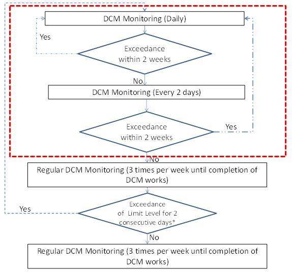
As illustrated in Chart 5.1, if no exceedance is recorded within the first two weeks, then the monitoring frequency can be reduced to every two days. If no exceedance is recorded after another two weeks, the intensive DCM monitoring will be terminated and DCM monitoring will continue as part of the regular DCM monitoring presented in Section 6.
5.6
Monitoring Procedures
Monitoring shall be conducted at mid-flood (within ± 1.75 hour of the predicted time) and mid-ebb (within ± 1.75 hour of the predicted time) tides. Samples should be taken at three depths (at 1m below surface, at mid-depth, and at 1m above bottom) for locations with water depth >6m. For locations with water depth between 3m and 6m, two depths (surface and bottom) should be taken. Locations with water depth <3m, only surface depth should be taken.
Two consecutive measurements of DO, DO%, pH, temperature (oC) turbidity (NTU), salinity (mg/L), and total alkalinity (ppm) should be taken in-situ according to the stated sampling method. Water samples for SS (mg/L), nutrient (mg/L) and heavy metals (µg/L) measurements should be collected at the same depths. Duplicate water samples should be taken and analysed.
5.7
Action and Limit Levels
The action and limit (AL) levels for DCM-specific water quality parameters during intensive DCM monitoring are defined in Table 5‑1.
Table 5‑1: Action and Limit Levels for DCM-specific Water Quality Parameters (Intensive DCM Monitoring)
|
Parameters |
Action Level |
Limit Level |
|
Temperature in °C |
1.8°C above the temperature recorded at representative control stations at the same tide of the same day |
2°C above the temperature recorded at representative control stations at the same tide of the same day |
|
Total Alkalinity in ppm |
95 percentile of baseline data or 120% of upstream control station at the same tide of the same day, whichever is higher |
99 percentile of baseline data or 130% of upstream control station at the same tide of the same day, whichever is higher |
|
Nutrient |
||
|
Ammonia (NH3) |
||
|
Unionised ammonia (NH3) (with 0.021 mg/L as the upper limit) |
||
|
Nitrite (NO2) |
||
|
Nitrate (NO3) |
||
|
TKN |
||
|
Total Phosphorus |
||
|
Reactive Phosphorus |
||
|
Heavy Metals |
||
|
Cadmium (Cd) |
||
|
Chromium (Cr) |
||
|
Copper (Cu) |
||
|
Nickel (Ni) |
||
|
Lead (Pb) |
||
|
Zinc (Zn) |
||
|
Arsenic (As) |
||
|
Silver (Ag) |
||
|
Mercury (Hg) |
Notes:
1. Non-compliance of water quality results when monitoring results is higher than the limits.
2. Depth-averaged results are used unless specified otherwise.
3. Baseline data to be adopted in the DCM monitoring are specified in the Baseline Monitoring Report.
For other parameters (DO, turbidity and SS), AL levels are defined in Table 5‑2.
Table 5‑2: Action and Limit Levels for Other Water Quality Parameters (Intensive DCM Monitoring)
|
Parameters |
Action Level |
Limit Level |
|
DO in mg/L (Surface and Middle) |
80% of upstream control station* at the same tide of the same day or 4 mg/l, whichever is lower |
70% of upstream control station* at the same tide of the same day or 4 mg/l, whichever is lower |
|
DO in mg/L (Bottom) |
80% of upstream control station* at the same tide of the same day or 2 mg/l, whichever is lower |
70% of upstream control station* at the same tide of the same day or 2 mg/l, whichever is lower |
|
Suspended Solids (SS) in mg/L |
120% of upstream control station* at the same tide of the same day |
130% of upstream control station* at the same tide of the same day |
|
Turbidity in NTU |
Note:
1. For DO measurement, non-compliance occurs when monitoring result is lower than the limits.
2. For parameters other than DO, non-compliance of water quality results when monitoring results is higher than the limits.
3. Depth-averaged results are used unless specified otherwise.
4. (*) Upstream control station refers to average of the two control station results, unless the difference between the two control station results is >25%, in which case the higher (for SS and turbidity) and lower (for DO) of the two shall apply.
5.8
Event and Action Plan
The actions in accordance with the Event and Action Plan in Table 5‑3 should be carried out if the water quality assessment criteria are exceeded at the impact monitoring stations.
Table 5‑3: Event and Action Plan for DCM Process during Intensive DCM Monitoring
|
|
Action |
|||
|
Event |
ET |
IEC |
AAHK / PM |
Contractor |
|
Action level being exceeded by one sampling day |
1. Repeat in-situ measurement to confirm findings; 2. Identify reasons for non-compliance and sources of impact; 3. Inform IEC and Contractor; 4. Check monitoring data, all plant, equipment and Contractor’s working methods; 5. Discuss mitigation measures with IEC and Contractor; 6. If not already undertaking daily monitoring, increase monitoring frequency in accordance with Chart 5.1. (applies to DCM-specific parameters only) |
1. Discuss with ET and Contractor on the mitigation measures; 2. Review proposals on mitigation measures submitted by Contractor and advise AAHK / PM accordingly; 3. Assess the effectiveness of the implemented mitigation measures. |
1. Discuss with IEC on the proposed mitigation measures; 2. Make agreement on the mitigation measures to be implemented; 3. Assess the effectiveness of the implemented mitigation measures. |
1. Inform AAHK / PM and confirm receipt of ET’s notification of the non-compliance in writing; 2. Rectify unacceptable practice; 3. Check all plant and equipment; 4. Provide report of the status and condition of plant, equipment and mitigation measures to ET; 5. Consider changes of working methods; 6. Discuss with ET and IEC and propose mitigation measures. |
|
Action Level being exceeded by more than two consecutive sampling days |
1. Repeat in-situ measurement to confirm findings; 2. Identify reasons for non-compliance and sources of impact; 3. Inform IEC and Contractor; 4. Check monitoring data, all plant, equipment and Contractor’s working methods; 5. Discuss mitigation measures with IEC and Contractor; 6. Ensure mitigation measures are implemented; 7. If not already undertaking daily monitoring, increase monitoring frequency in accordance with Chart 5.1. (applies to DCM- specific parameters only) |
1. Discuss with ET and Contractor on the mitigation measures; 2. Review proposals on mitigation measures submitted by Contractor and advise AAHK / PM accordingly; 3. Assess the effectiveness of the implemented mitigation measures. |
1. Discuss with IEC on the proposed mitigation measures; 2. Make agreement on the mitigation measures to be implemented; 3. Assess the effectiveness of the implemented mitigation measures. |
1. Inform AAHK / PM and confirm receipt of ET’s notification of the non-compliance in writing; 2. Rectify unacceptable practice; 3. Check all plant and equipment; 4. Provide report of the status and condition of plant, equipment and mitigation measures to ET; 5. Consider changes of working methods; 6. Discuss with ET and IEC and propose mitigation measures to IEC and AAHK / PM within 3 working days; 7. Implement the agreed mitigation measures. 8. As directed by AAHK / PM, to slow down all or part of the construction activities. |
|
Limit Level being exceeded by one sampling day |
1. Repeat in-situ measurement to confirm findings; 2. Identify reasons for non-compliance and sources of impact; 3. Inform IEC, Contractor and EPD; 4. Check monitoring data, all plant, equipment and Contractor’s working methods; 5. Discuss mitigation measures with IEC, AAHK / PM and Contractor; 6. Ensure mitigation measures are implemented; 7. If not already undertaking daily monitoring, increase monitoring frequency in accordance with Chart 5.1. (applies to DCM- specific parameters only) |
1. Discuss with ET and Contractor on the mitigation measures; 2. Review proposals on mitigation measures submitted by Contractor and advise AAHK / PM accordingly; 3. Assess the effectiveness of the implemented mitigation measures. |
1. Discuss with IEC, ET and Contractor on the proposed mitigation measures; 2. Request Contractor to critically review the working methods; 3. Make agreement on the mitigation measures to be implemented; 4. Assess the effectiveness of the implemented mitigation measures. |
1. Inform AAHK / PM and confirm receipt of ET’s notification of the non-compliance in writing; 2. Rectify unacceptable practice; 3. Check all plant and equipment; 4. Provide report of the status and condition of plant, equipment and mitigation measures to ET; 5. Consider changes of working methods; 6. Discuss with ET, IEC and AAHK / PM and propose mitigation measures to IEC and AAHK / PM within three working days; 7. Implement the agreed mitigation measures. |
|
Limit Level being exceeded by more than one consecutive sampling days |
1. Repeat in-situ measurement to confirm findings; 2. Identify reasons for non-compliance and sources of impact; 3. Inform IEC, Contractor and EPD; 4. Check monitoring data, all plant, equipment and Contractor’s working methods; 5. Discuss mitigation measures with IEC, AAHK / PM and Contractor; 6. Ensure mitigation measures are implemented; 7. If not already undertaking daily monitoring, increase monitoring frequency in accordance with Chart 5.1. (applies to DCM- specific parameters only) |
1. Discuss with ET and Contractor on the mitigation measures; 2. Review proposals on mitigation measures submitted by Contractor and advise AAHK / PM accordingly; 3. Assess the effectiveness of the implemented mitigation measures. |
1. Discuss with IEC, ET and Contractor on the proposed mitigation measures; 2. Request contractor to critically review the working methods; 3. Make agreement on the mitigation measures to be implemented; 4. Assess the effectiveness of the implemented mitigation measures; 5. Consider and instruct, if necessary, the Contractor to slow down or to stop all or part of the construction activities until no exceedance of limit level. |
1. Inform AAHK / PM and confirm receipt of ET’s notification of the non-compliance in writing; 2. Rectify unacceptable practice; 3. Check all plant and equipment; 4. Provide report of the status and condition of plant, equipment and mitigation measures to ET; 5. Consider changes of working methods; 6. Discuss with ET, IEC and AAHK / PM and propose mitigation measures to IEC and AAHK / PM within three working days; 7. Implement the agreed mitigation measures; 8. As directed by AAHK / PM, to stop all or part of the construction activities. |
Notes:
DCM- specific parameters refers to alkalinity, temperature, nutrients and heavy metals only
5.9
Reporting
Findings from the initial intensive DCM monitoring will be used to review the monitoring requirements for all parameters for regular DCM monitoring. The findings and recommendations shall be compiled as a separate Report and verified by IEC before submission to EPD for agreement. For any re-initiated intensive DCM monitoring, these shall be reported as part of the relevant Monthly EM&A Report, and the subsequent Quarterly and Annual EM&A Report. The reporting requirements shall follow the relevant requirements specified in the Updated EM&A Manual.
6.1
Purpose
The purpose of the regular DCM monitoring is to maintain a check on the environmental acceptability of the full scale DCM works throughout the duration of DCM works, and to provide a mechanism for re-initiation of intensive DCM monitoring in the event of exceedances in water quality limits arising from the DCM activities. The details of the regular DCM monitoring may be subject to changes depending on the findings and recommendations of the initial intensive DCM monitoring review report.
6.2
Timing
Prior to commencement of initial intensive DCM monitoring, early regular DCM monitoring will be conducted to maintain a check on the early DCM works until initial intensive DCM monitoring commences. After completion of the initial intensive DCM monitoring, the regular DCM monitoring will continue for the remaining duration of the DCM works. Exact timing of commencement of the regular DCM monitoring programme is subject to the date of commencement of DCM works, and the date of completion of initial intensive DCM monitoring. Regular DCM monitoring would be temporarily halted whenever intensive DCM monitoring is re-initiated, and would re-commence once the intensive DCM monitoring process has been completed with no further exceedances detected.
6.3
Parameters for Regular DCM Monitoring
During regular DCM monitoring, DO, DO%, pH, temperature, salinity, turbidity, SS, total alkalinity and two representative heavy metals will be monitored. The selection criteria for determining the representative heavy metals include:
1. Low natural (baseline) concentrations in the marine environment
2. Present in elevated concentrations in the CMPs (based on past vibrocores taken from the CMP)
3. Concentrations in the CMPs should be higher than in non- CMP areas
4. Not associated with strong temporal variations and/or external influences (e.g. Pearl River Delta (PRD) discharges, construction activities by concurrent projects)
As specified in the Updated EM&A Manual, the two representative heavy metals shall be proposed taking into account the findings of the initial intensive DCM monitoring. However, for the early regular DCM monitoring, such findings are not yet available, hence for the early regular DCM monitoring, the proposed representative heavy metals would be based on a broad review of past information only, and the final recommendation for the two representative heavy metals would be determined after completion of the initial intensive DCM monitoring.
For the early regular DCM monitoring, the selection criteria above was compared with each heavy metal and the broad findings are summarised in Table 6.1.
Table 6.1: Broad Comparison of Heavy Metals against the Selection Criteria
|
Parameter |
Criteria 1 |
Criteria 2 |
Criteria 3 |
Criteria 4 |
|
|
(marine baseline) |
(CMPs) |
(non-CMPs) |
(temporal / external influence) |
|
Cadmium |
Low / non-detectable baseline concentrations |
Marginally elevated concentrations in CMPs |
Lower concentration than CMPs |
Limited temporal / external influence |
|
Chromium |
Low / non-detectable baseline concentrations |
Elevated concentrations in CMPs |
Lower concentration than CMPs |
Limited temporal / external influence |
|
Copper |
Notable concentrations in baseline marine waters |
Elevated concentrations in CMPs |
Lower concentration than CMPs |
Associated with discharges from PRD and exhibits some temporal variability |
|
Nickel |
Notable concentrations in baseline marine waters |
Elevated concentrations in CMPs |
Lower concentration than CMPs |
Limited external influence with some temporal variability |
|
Lead |
Low / non-detectable baseline concentrations |
Marginally elevated concentrations in CMPs |
Similar concentration to CMPs |
Associated with discharges from PRD but exhibits limited temporal variability |
|
Zinc |
Notable concentrations in baseline marine waters |
Elevated concentrations in CMPs |
Partially higher concentration than CMPs |
Associated with discharges from PRD and exhibits some temporal variability |
|
Arsenic |
Notable concentrations in baseline marine waters |
Elevated concentrations in CMPs |
Higher concentration than CMPs |
Associated with discharges from PRD and exhibits some temporal variability |
|
Silver |
Low / non-detectable baseline concentrations |
Non-detectable in CMPs |
Higher concentration than CMPs |
Limited temporal / external influence |
|
Mercury |
Low / non-detectable baseline concentrations |
Non-detectable in CMPs |
Non-detectable in CMPs |
Limited temporal / external influence |
Source:
Criteria 1 – based on general review of baseline results from 3RS baseline water quality monitoring
Criteria 2 – based on general review of vibrocore samples taken from CMPs (as documented in the approved 3RS EIA report)
Criteria 3 – based on general comparison of vibrocore results between CMPs and non-CMPs (as documented in the approved 3RS EIA report)
Criteria 4 – based on general review of 3RS baseline results and general literature
Note: shaded cells denotes that the specified criteria is not fully meet
Based on the broad findings summarised in Table 6.1, chromium is clearly identified as meeting all criteria requirements, hence is proposed as one of the representative heavy metals. Of the remaining parameters, cadmium and nickel meet three out of four criteria, while all other parameters fail at least two criteria, hence are less suitable. Given that nickel shows more notable elevated concentrations in the CMPs compared to cadmium, detection of nickel in concentrations higher than baseline and/or same day control station results is more likely to indicate release from CMPs.
Based on this broad analysis, the two representative heavy metals initially selected and proposed for early regular DCM monitoring are chromium and nickel. The representability of these two heavy metals for the regular DCM monitoring to be conducted after completion of the initial intensive DCM monitoring will be reviewed and amended where appropriate once the findings from the initial intensive DCM monitoring are completed. The final two heavy metals will be proposed by ET and agreed with IEC.
6.4
Monitoring Locations
Water quality for the regular DCM monitoring shall be measured at the stationary Control (C) and Impact (IM) stations as listed in Table 6‑2 and illustrated in Figure 6.1. The locations of these C and IM stations are the same as those for the overall 3RS Project. DO, DO%, pH, temperature, salinity, turbidity, SS, total alkalinity and the two representative heavy metals should be measured at all stations.
Table 6‑2: Water Quality Monitoring Stations for Regular DCM Monitoring
|
Monitoring Stations |
Coordinates |
|
DCM Specific Parameters |
Other Parameters |
|
Easting |
Northing |
|||
|
C1 |
804247 |
815620 |
Total Alkalinity and 2 Representative Heavy Metals
Note For early regular DCM monitoring, chromium and nickel are proposed as the two representative heavy metals. For regular DCM monitoring after completion of initial intensive DCM monitoring, the two representative heavy metals will be further reviewed and amended where appropriate. |
DO, DO%, pH, Temperature, Salinity, Turbidity, SS |
|
C2 |
806945 |
825682 |
||
|
C3 |
817803 |
822109 |
||
|
IM1 |
806458 |
818351 |
||
|
IM2 |
806193 |
818852 |
||
|
IM3 |
806019 |
819411 |
||
|
IM4 |
805039 |
819570 |
||
|
IM5 |
804924 |
820564 |
||
|
IM6 |
805828 |
821060 |
||
|
IM7 |
806835 |
821349 |
||
|
IM8 |
807838 |
821695 |
||
|
IM9 |
808811 |
822094 |
||
|
IM10 |
809838 |
822240 |
||
|
IM11 |
810545 |
821501 |
||
|
IM12 |
811519 |
821162 |
|
Figure 6.1: Location of Monitoring Stations for Regular DCM Works |
|
|

6.5
Monitoring Frequency and Duration
Monitoring frequency and duration is linked to a feedback loop mechanism that enables the regular DCM monitoring to be changed to intensive DCM monitoring should there be any exceedances in water quality limit levels for the DCM-specific parameters. The feedback loop mechanism for DCM Monitoring is shown in Chart 6.1.
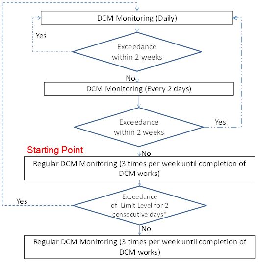
As illustrated in Chart 6.1, regular DCM monitoring of three times per week will continue for the duration of DCM works unless there is any exceedance of the limit levels for total alkalinity and the two representative heavy metals for two consecutive sampling days and such exceedance is confirmed by the ET (with verification by the IEC) to be a result of the DCM works. If such instances arise, intensive DCM monitoring will be re-initiated as shown in Chart 6.1 and will follow the procedures described in Section 5. Regular DCM monitoring will only resume once the intensive DCM monitoring process has been completed with no further exceedances detected.
6.6
Monitoring Procedures
Monitoring shall be conducted at mid-flood (within ± 1.75 hour of the predicted time) and mid-ebb (within ± 1.75 hour of the predicted time) tides. Samples should be taken at three depths (at 1m below surface, at mid-depth, and at 1m above bottom) for locations with water depth >6m. For locations with water depth between 3m and 6m, two depths (surface and bottom) should be taken. Locations with water depth <3m, only surface depth should be taken.
Two consecutive measurements of DO, DO%, pH, temperature (oC) turbidity (NTU), salinity (mg/L), total alkalinity (ppm) should be taken in-situ according to the stated sampling method. Water samples for SS (mg/L) and heavy metals (µg/L) measurements should be collected at the same depths. Duplicate water samples should be taken and analysed.
6.7
Action and Limit Levels
The action and limit levels for DCM-specific water quality parameters during regular DCM water quality monitoring are defined in Table 6‑3. Note that for other parameters (e.g. DO, turbidity and SS), the AL levels and associated Event and Action Plan for general water quality monitoring as specified in the Baseline Water Quality Monitoring Report shall apply.
Table 6‑3: Action and Limit Levels for DCM-specific Water Quality Parameters (Regular DCM Monitoring)
|
Parameters |
Action Level |
Limit Level |
|
Total Alkalinity in ppm |
95 percentile of baseline data or 120% of upstream control station at the same tide of the same day, whichever is higher |
99 percentile of baseline data or 130% of upstream control station at the same tide of the same day, whichever is higher |
|
2 Representative Heavy Metals |
Notes:
1. Non-compliance of water quality results when monitoring results is higher than the limits.
2. Depth-averaged results are used unless specified otherwise.
3. Baseline data to be adopted in the DCM monitoring are specified in the Baseline Monitoring Report.
6.8
Event and Action Plan
The actions in accordance with the Event and Action Plan in Table 6‑4 should be carried out if the water quality assessment criteria for DCM-specific water quality parameters are exceeded at the impact monitoring stations.
Table 6‑4: Event and Action Plan for DCM Process during Regular DCM Monitoring
|
|
Action |
|||
|
Event |
ET |
IEC |
AAHK / PM |
Contractor |
|
Action level being exceeded by one sampling day |
1. Repeat in-situ measurement to confirm findings; 2. Identify reasons for non-compliance and sources of impact; 3. Inform IEC and Contractor; 4. Check monitoring data, all plant, equipment and Contractor’s working methods; 5. Discuss mitigation measures with IEC and Contractor; 6. Repeat monitoring on the day after the exceedance. |
1. Discuss with ET and Contractor on the mitigation measures; 2. Review proposals on mitigation measures submitted by Contractor and advise AAHK / PM accordingly; 3. Assess the effectiveness of the implemented mitigation measures. |
1. Discuss with IEC on the proposed mitigation measures; 2. Make agreement on the mitigation measures to be implemented; 3. Assess the effectiveness of the implemented mitigation measures. |
1. Inform AAHK / PM and confirm receipt of ET’s notification of the non-compliance in writing; 2. Rectify unacceptable practice; 3. Check all plant and equipment; 4. Provide report of the status and condition of plant, equipment and mitigation measures to ET; 5. Consider changes of working methods; 6. Discuss with ET and IEC and propose mitigation measures. |
|
Action Level being exceeded by more than two consecutive sampling days |
1. Repeat in-situ measurement to confirm findings; 2. Identify reasons for non-compliance and sources of impact; 3. Inform IEC and Contractor; 4. Check monitoring data, all plant, equipment and Contractor’s working methods; 5. Discuss mitigation measures with IEC and Contractor; 6. Ensure mitigation measures are implemented; 7. Repeat monitoring on the day after the exceedance and prepare to increase the monitoring frequency to daily. |
1. Discuss with ET and Contractor on the mitigation measures; 2. Review proposals on mitigation measures submitted by Contractor and advise AAHK / PM accordingly; 3. Assess the effectiveness of the implemented mitigation measures. |
1. Discuss with IEC on the proposed mitigation measures; 2. Make agreement on the mitigation measures to be implemented; 3. Assess the effectiveness of the implemented mitigation measures. |
1. Inform AAHK / PM and confirm receipt of ET’s notification of the non-compliance in writing; 2. Rectify unacceptable practice; 3. Check all plant and equipment; 4. Provide report of the status and condition of plant, equipment and mitigation measures to ET; 5. Consider changes of working methods; 6. Discuss with ET and IEC and propose mitigation measures to IEC and AAHK / PM within 3 working days; 7. Implement the agreed mitigation measures. 8. As directed by AAHK / PM, to slow down all or part of the construction activities. |
|
Limit Level being exceeded by one sampling day |
1. Repeat in-situ measurement to confirm findings; 2. Identify reasons for non-compliance and sources of impact; 3. Inform IEC, Contractor and EPD; 4. Check monitoring data, all plant, equipment and Contractor’s working methods; 5. Discuss mitigation measures with IEC, AAHK / PM and Contractor; 6. Ensure mitigation measures are implemented; 7. Repeat monitoring on the day after the exceedance. |
1. Discuss with ET and Contractor on the mitigation measures; 2. Review proposals on mitigation measures submitted by Contractor and advise AAHK / PM accordingly; 3. Assess the effectiveness of the implemented mitigation measures. |
1. Discuss with IEC, ET and Contractor on the proposed mitigation measures; 2. Request Contractor to critically review the working methods; 3. Make agreement on the mitigation measures to be implemented; 4. Assess the effectiveness of the implemented mitigation measures. |
1. Inform AAHK / PM and confirm receipt of ET’s notification of the non-compliance in writing; 2. Rectify unacceptable practice; 3. Check all plant and equipment; 4. Provide report of the status and condition of plant, equipment and mitigation measures to ET; 5. Consider changes of working methods; 6. Discuss with ET, IEC and AAHK / PM and propose mitigation measures to IEC and AAHK / PM within three working days; 7. Implement the agreed mitigation measures. |
|
Limit Level being exceeded by more than one consecutive sampling days |
1. Repeat in-situ measurement to confirm findings; 2. Identify reasons for non-compliance and sources of impact; 3. Inform IEC, Contractor and EPD; 4. Check monitoring data, all plant, equipment and Contractor’s working methods; 5. Discuss mitigation measures with IEC, AAHK / PM and Contractor; 6. Ensure mitigation measures are implemented; 7. Re-initiate the intensive DCM monitoring in accordance with Chart 6.1. |
1. Discuss with ET and Contractor on the mitigation measures; 2. Review proposals on mitigation measures submitted by Contractor and advise AAHK / PM accordingly; 3. Assess the effectiveness of the implemented mitigation measures. |
1. Discuss with IEC, ET and Contractor on the proposed mitigation measures; 2. Request contractor to critically review the working methods; 3. Make agreement on the mitigation measures to be implemented; 4. Assess the effectiveness of the implemented mitigation measures; 5. Consider and instruct, if necessary, the Contractor to slow down or to stop all or part of the construction activities until no exceedance of limit level. |
1. Inform AAHK / PM and confirm receipt of ET’s notification of the non-compliance in writing; 2. Rectify unacceptable practice; 3. Check all plant and equipment; 4. Provide report of the status and condition of plant, equipment and mitigation measures to ET; 5. Consider changes of working methods; 6. Discuss with ET, IEC and AAHK / PM and propose mitigation measures to IEC and AAHK / PM within three working days; 7. Implement the agreed mitigation measures; 8. As directed by AAHK / PM, to stop all or part of the construction activities. |
6.9
Reporting
Findings from the regular DCM monitoring shall be reported as part of the Monthly, Quarterly and Annual EM&A Report. The reporting requirements shall follow the relevant requirements specified in the Updated EM&A Manual.
7.1
General
Mitigation measures for the 3RS Project have been specified in the approved EIA report. It should be noted that the use of DCM at CMP areas is itself a mitigation measure recommended in the approved EIA report for protection of water quality and marine ecology. The mitigation measures listed in this Section are thus restricted to those that are recommended for ensuring the DCM process and activities themselves do not cause adverse water quality impact and disturbance to marine mammals.
7.2
Mitigation Measures for Water Quality
Mitigation measures recommended for protecting water quality due to DCM activities include the following:
¡ Sand blanket laying over the seabed prior to DCM activities.
¡ Wash water from cleaning of the drilling shaft should be appropriately treated before discharge.
¡ The Contractor should ensure any wastewater discharge from the DCM activities meets the relevant requirements of Water Pollution Control Ordinance (WPCO) / the Technical Memorandum issued under WPCO before discharge.
¡ No direct discharge of contaminated water is permitted.
¡ No discharge of the cement mixed materials directly into the marine environment is allowed.
¡ Implementation of the Spill Response Plan for the 3RS Project (details refer to the approved Spill Response Plan available on the dedicated 3RS website http://env.threerunwaysystem.com/en/ep-submissions.html)
7.3
Mitigation / Precautionary Measures for Marine Mammals
Mitigation / precautionary measures recommended for protecting marine mammals due to DCM activities include the following:
¡ Implementation of the Dolphin Exclusion Zone Plan for the 3RS Project (details refer to the approved Dolphin Exclusion Zone Plan available on the dedicated 3RS website http://env.threerunwaysystem.com/en/ep-submissions.html)
¡ Implementation of the Spill Response Plan for the 3RS Project (details refer to the approved Spill Response Plan available on the dedicated 3RS website http://env.threerunwaysystem.com/en/ep-submissions.html)
¡ Implementation of the Marine Travel Routes and Management Plan for Construction and Associated Vessels for the 3RS Project (details refer to the approved Marine Travel Routes and Management Plan for Construction and Associated Vessels available on the dedicated 3RS website http://env.threerunwaysystem.com/en/ep-submissions.html)